Share
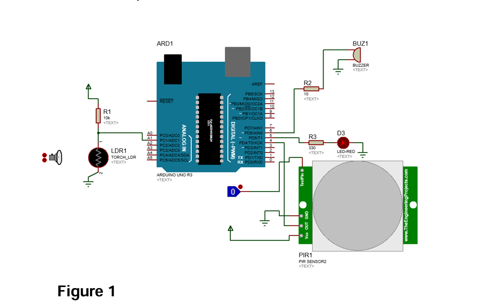
The circuit shown in Figure 2 is based on Arduino and is designed to control the movement in a restricted area. It includes two inputs – an LDR sensor and a PIR motion sensor – and two outputs: an LED that illuminates when the LDR sensor detects darkness in the area, and a buzzer that produces a sound when the PIR sensor is triggered by the movement of a person in the restricted area. Build the circuit of Figure 1 in Proteus? b) Using Arduino IDE, write a program that can read the input states and give the appropriate outputs based on the following conditions: Condition 1: If the PIR motion sensor is triggered and the LDR sensor detects brightness, sounds only the speaker. Condition 2: If the PIR Mention sensor is not triggered and the LDR sensor detects darkness, turn ON the LED_RED. Condition 3: If the PIR motion sensor is triggered and the LDR sensor detects dark, both LED_RED and Speaker are switched ON Condition 4: If the Switch (PIR motion sensor) is not triggered and the LDR sensor is in brightness, no output is provided c) Upload the program written in (b) in the proteus and test the circuit functionality.
ReportQuestion
Please briefly explain why you feel this question should be reported.
dddddcccxx
Leave an answer