Share
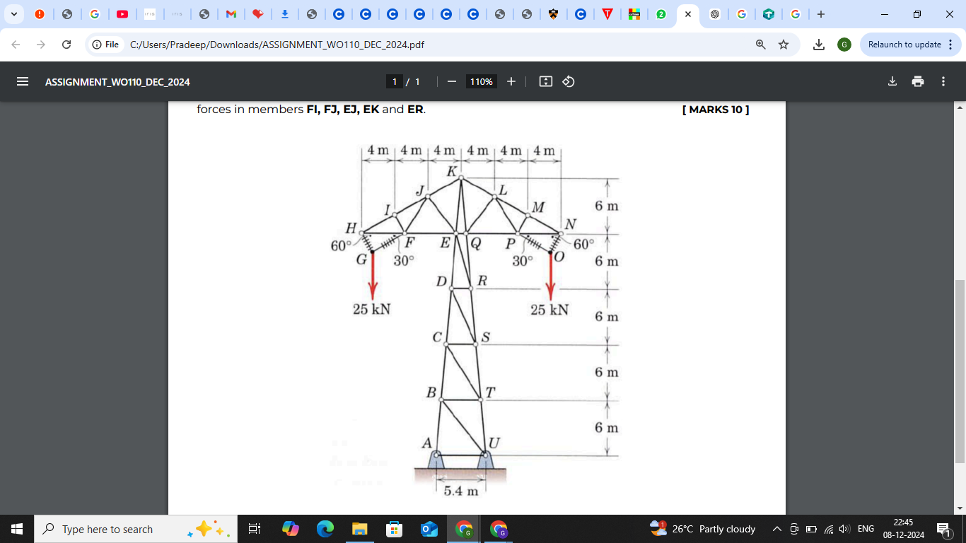
)A design model for a transmission line tower is shown in the gure. Members GH, FG, OP and NO are insulated cables; all other members are steel bars. For the loading shown, compute the forces in members FI, FJ, EJ, EK and ER.
ReportQuestion
Please briefly explain why you feel this question should be reported.
Answer ( 1 )
Please briefly explain why you feel this answer should be reported.