Share
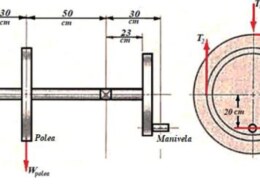
30 hp are supplied at 75 cm gear by means of a pinion, as shown in figure 1. In the pulley of 60 cm 20 hp is taken out and, in the 20cm crank 10 hp are taken out. The mass of the pulley is 450 kg, in order to provide some flywheel effect and rotates at 300 rev/min. The arrangement of elements and stresses in the belt are shown in Figure 1. The tangential force is Tt = 1900 kN and the radial force is Tr.= 690 N of stresses in the band is 4:1. Loads are applied with moderate shock with kf = kfs = 1.97 and kfm = kfsm = 1.54. For the 30 mm diameter shaft in figure 1, determine: a) the shear and bending moment diagrams in the vertical, horizontal and total planes; b) what is the bending moment at the bearing location that is between the gear and pulley, in kN m? c) What is the maximum bending moment on the shaft, in kN m? d) Which Are the maximum shear and normal stresses and where do they occur?
ReportQuestion
Please briefly explain why you feel this question should be reported.
30 hp are supplied at 75 cm gear by means of a pinion, as shown in figure 1. In the pulley of 60
cm 20 hp is taken out and, in the 20cm crank 10 hp are taken out. The mass of the pulley is 450 kg, in order to provide some flywheel effect and rotates at 300 rev/min. The arrangement of elements and stresses in the belt are shown in Figure 1. The tangential force is Tt = 1900 kN and the radial force is Tr.= 690 N of stresses in the band is 4:1. Loads are applied with moderate shock with kf = kfs = 1.97 and kfm = kfsm = 1.54. For the 30 mm diameter shaft in figure 1, determine: a) the shear and bending moment diagrams in the vertical, horizontal and total planes; b) what is the bending moment at the bearing location that is between the gear and pulley, in kN m? c) What is the maximum bending moment on the shaft, in kN m? d) Which Are the maximum shear and normal stresses and where do they occur?
Se suministran 30 hp a engrane de 75 cm por medio de un piñón, como se muestra en la figura 1. En la polea de 60 cm se sacan 20 hp y, en la manivela de 20 cm se sacan 10 hp. La masa de la polea es de 450 kg, con el fin de proporcionar algún efecto de volante y gira a 300 rev/min. La disposición de los elementos y las tensiones en la correa se muestran en la figura 1. La fuerza tangencial es Tt = 1900 kN y la fuerza radial es Tr.= 690 N La relación de tensiones en la banda es 4:1. Las cargas se aplican con choque moderado con kf = kfs = 1,97 y kfm = kfsm = 1,54.
Para el eje de 30 mm de diámetro de la figura 1, determine: a) los diagramas de cortante y momento flexionante en los planos vertical, horizontal y totales; b) ¿Cuál es el momento flexionante en la ubicación del cojinete que está entre el engrane y la polea, en kN m? c) ¿Cuál es el momento flexionante máximo sobre el eje, en kN m? d) ¿Cuáles son los esfuerzos cortante y normal máximos y dónde se presentan?

Answer ( 1 )
Please briefly explain why you feel this answer should be reported.